Background
As one of my first projects where I used a "popular" programming language and also integrated it with electronics, the RGB LED Controller is a project worth showing as it still works to this day, 2022-08-17.
In 7th grade, I wanted to get on the RGB hype train since my brother just bought the GTX 1070 STRIX and was flexing his breathing RGB lighting, so I wanted to DIY my own solution, since I only had these other choices for RGB:
- Insanely expensive Corsair/Noctua/ASUS/Someone else's ready-to-go solution. Very easy, made for custom PCs, plugs right into your motherboard USB headers, and comes with software to configure it. The top-tier choice, if you have money.
- Another GTX 1070 STRIX.
- Some strange RGB LED strip off eBay or Amazon that comes with an IR remote for easy color changing. Not fun, but likely cheaper now since prices have dropped. Doesn't come with breathing lights, which I really wanted.
- DIY the first option, having to do everything from scratch.
Going DIY
As you can tell, I chose the last option, soldering an Arduino Nano to a perfboard with 3 N-channel MOSFETs and an RGB LED strip from Adafruit (link may not reflect the same product I purchased) with some wires sticking into my power supply's leftover PCIe power pins in order to steal 12V from somewhere.
The Schematic
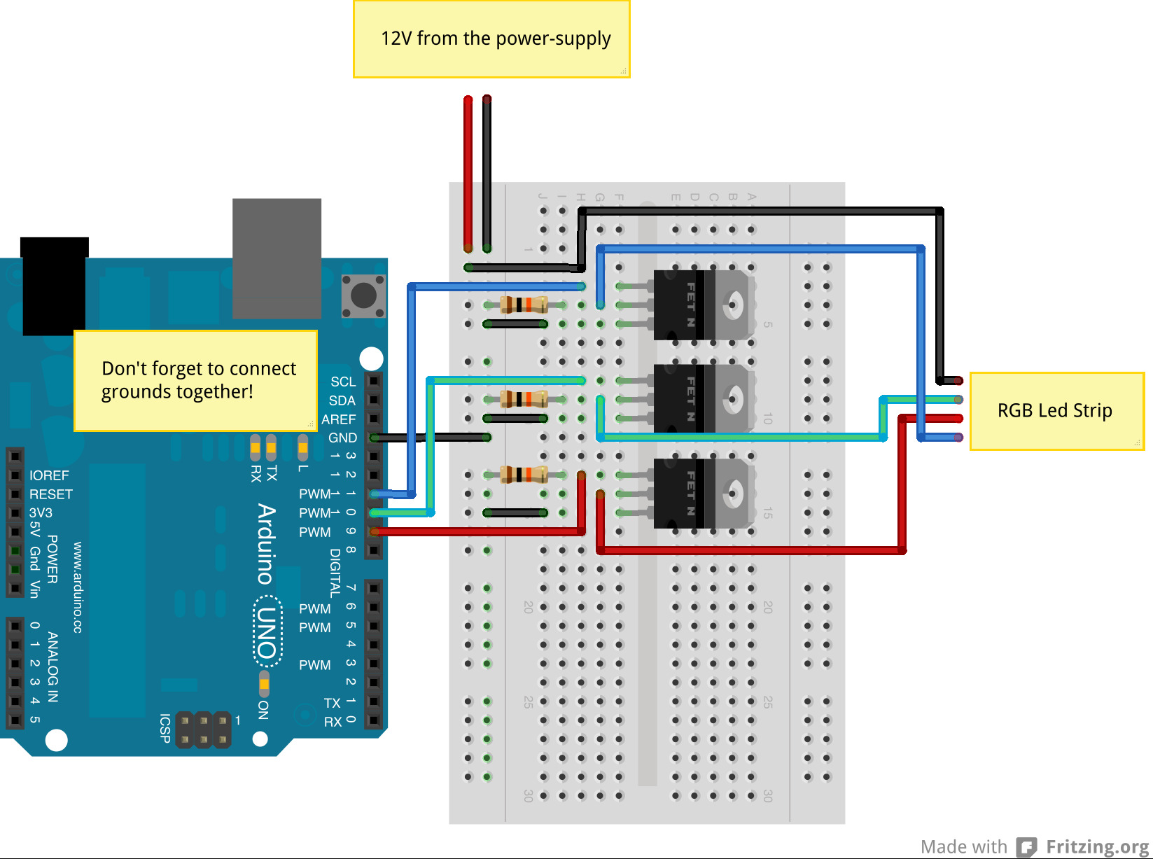
Since I'm literally just connecting an Arduino Nano to an RGB LED strip, this was going to be extremely easy considering there are so many schematics online. Here's one:

It's basically this but for a Nano
For connecting to my PC, I took a miniUSB cable and just chopped the wires for the data pins and soldered on female jumper headers to plug into my motherboard's USB header. This way I could control it from my PC!
The Result
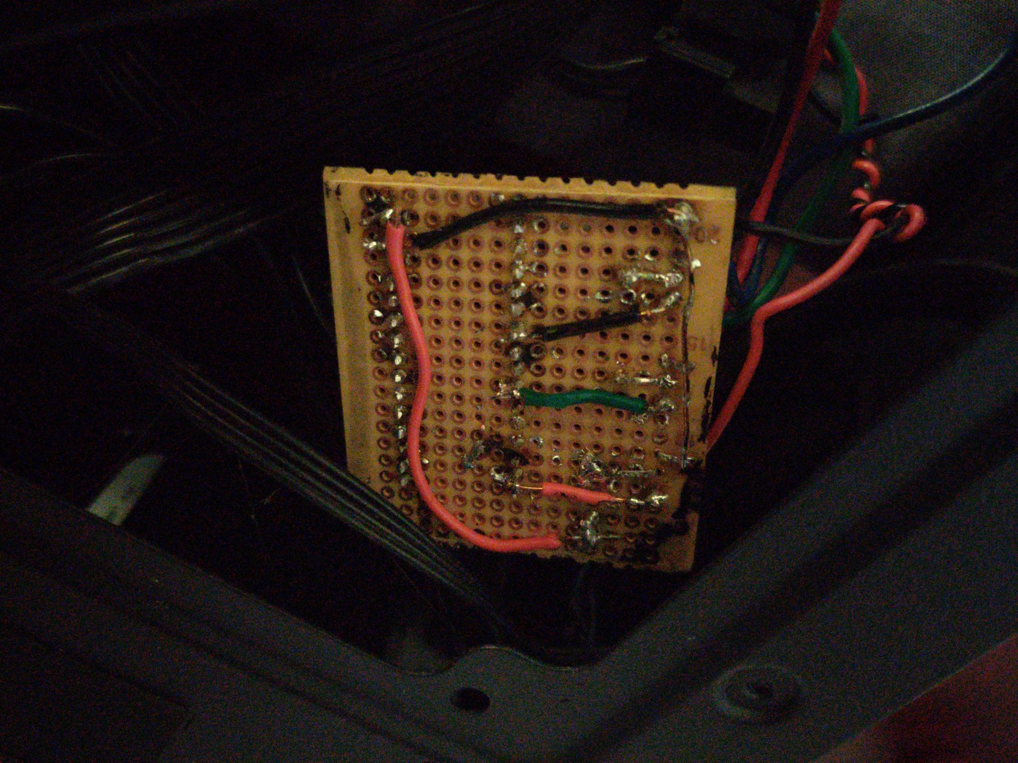
Yeah, so it's not the best looking, but it was by 13-year-old me:

Do note that this photo was taken in 2022, inside my Node 202 PC case.
Do also note that I don't feel like disassembling my PC to take a photo of the component side. Sorry guys, but just imagine a Nano soldered to perfboard with 3 MOSFETS and an RGB LED strip and a mystery black and red wire coming out. The mystery wires are power wires that plug into a spare PCI-E power connector, of course.
Software Time
However, software is still missing, so I had to write my own from scratch.
Arduino Sketch
For communication, I decided to use the Firmata protocol since it's something widely used for talking to Arduinos. I don't have to create my own command specification for talking to the Arduino this way.
I just uploaded the StandardFirmata sketch and decided to do all my logic on my PC.
PC Logic - Where the magic happens
Having just learned C# from a project I made for my Minecraft server, which I unfortunately can't find right now (TODO: Find server sys tray viewer), I decided to make a Windows Forms app since it was gonna be easy, right?
Wrong!
I wanted my RGB LED strip to react to the following:
- React to my PC Sound
- Show a static color
- Fade in and out from a color, making a breathing effect, because my brother wouldn't stop flexing his GPU breathing blue
- Strobing color
- Cycle between rainbow colors
- React based on CPU temperature
Those are all trivial except for PC sound and CPU temperature. Eventually, I found the OpenHardwareLib library, as well as the NAudio library, and I somehow pulled that off in the end.
Many comments later, I finished, and here is the code: https://github.com/Noorquacker/RGBLEDController. It's got a lot of cringe comments from 13-year-old me, so don't be too surprised if you find something weird.
The Conclusion
So, here's the thing.
I wrote a Windows Forms app.
And I switched to Linux about 1.5 years later.
So I decided to hardcode the rainbow cycle into the Arduino Nano and leave it. And it's been working for nearly 6 years now.
I don't have any plans on porting this to Linux even though I would definitely rather rewrite it in Rust. I have much cooler project ideas, and I enjoy the rainbow color cycle anyways. Sometimes, the simplest solutions are the best.
And by sometimes, I mean nearly all the time.
